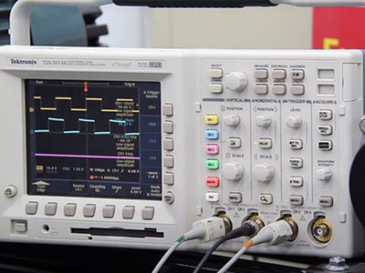

Encoder signal outputs are generated by a rotary encoder when the shaft or bore rotates. Incremental encoders generate a set number of pulses per revolution while an absolute encoder generates a stream of bits corresponding to discrete position.
The performance of an incremental encoder is only as good as its signal. The readout device needs to receive a stream of symmetrical square wave pulses of sufficient amplitude to be detected. In theory, that just requires powering up the encoder and connecting a few wires. In reality, many error sources contribute to signal issues that can do everything from reducing timing accuracy to making the output impossible to detect. Here, we present a brief tutorial on encoder signals, common signal anomalies, what causes them and how to fix them.
With the exception of the index channel, the channels of an incremental encoder code disc are patterned to generate a signal with a 50-50 duty cycle (see below). That means that 50% of the waveform should be high (0° to 180°) and 50% should be low (180° to 360°). In other words, it should be symmetrical.

In many cases, encoder performance depends on the relative phasing between channels. Quadrature encoders, for example, leverage an A channel and a B channel offset from one another by 90° to distinguish between clockwise and counterclockwise rotation. The use of a channel and its complement (e.g. A and A-Not), two signals 180° out of phase, provides a method for filtering out noise spikes. The index channel is designed to generate a single pulse per revolution, but its position relative to the other channels varies depending on the system.
Double check the signal for the expected performance. For quadrature encoders, the phasing should conform with your rotation convention. When the system rotates the opposite direction, the relative position of the signals should switch, indicating a change in the direction of rotation.
The expected phasing for the index signal varies depending upon the encoder. Gated-index encoders pass the index signal through a logic gate that synchronizes it with the B-Not signal. In other words, when the B channel goes low, the index channel goes high. When the B channel goes high again, the index channel goes low. In some cases, the index is not gated. Consult the specific encoder datasheet to determine exact pulse width and timing.